| VIII. USING THE NAVIGATION INSTRUMENTS
VOR Receiver One VOR receiver, used correctly and operating properly, will provide positive and accurate course guidance between most airports on or off Federal Airways. Dual VOR receivers will reduce your en-route workload considerably. VOR in combination with DME will provide the navigational information that, without these aids, requires constant division of attention between basic aircraft control, computation, navigation, and coordination with Air Traffic Control. There are several common misconceptions about Omni, including the
notions that the VOR receiver automatically solves your problems of course
orientation and drift correction; that a "TO" indication always means that your
aircraft is heading toward the station; that you always turn toward the
direction of needle displacement to intercept a desired course; or that a
fluctuating TO/FROM indication necessarily means station passage. As you will
see, each component of the VOR indicator and tuning apparatus operates in
relation to the other components. The indicator provides precisely the
information you set it up to measure, the position of your aircraft antenna with
respect to a selected magnetic course to or from the VOR transmitter. Correctly
used, omni simplifies your navigation problems and reduces the time and effort
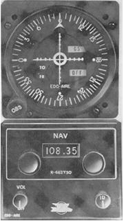
necessary for their solution. Tuning. The on/off/volume control turns on the navigation receiver and controls the audio volume. The volume control has no effect on the operation of the VOR indicator. With the volume set at a comfortable level and the "ID" tone control adjusted, the station is identified by code or automatic voice transmission. Positive identification of the VOR station is important since a Flight Service Station (FSS) may transmit messages simultaneously over a number of "remoted" VOR facilities. If you hear "Jonesville Area Radio" transmitting a weather broadcast, you may be tuned to Jonesville Omni or to any of a number of VOR stations remoted from Jonesville FSS. If no station identification signal is heard, the facility has been taken over by maintenance for tune-up or repair. Figure 8-1. VOR/Localizer receiver.
Frequency Selection. The left Knob selects Megahertz; the right knob selects tenth-Megahertz and Kilohertz. This model covers the 200-channel VOR/LOC frequency range of 108.00 MHz through 117.95 MHz with 50 kHz spacing. Aeronautical charts show VOR frequencies as well as the coded identification. Omni-Bearing Selector (OBS). The OBS knob drives the omni-bearing indicator dial for selection of any desired radial under the course index, with the reciprocal of the course shown under the lower index. With the receiver warmed up and a usable signal received, the "OFF" flag will disappear, and the course deviation indicator (CDI) will move to a stable position. If a steady flag does not appear in either the "TO" or "FROM" window and the CDI shows full deflection, rotate the OBS knob until the CDI centers and a positive "TO" or "FROM" is indicated. The needle will eventually center by rotation of the OBS and dial in either direction. To center the needle quickly, note the "TO" or "FROM" indication. With a "TO" indication, rotate the OBS toward the deflection, counterclockwise with a left deflection and clockwise with a right deflection. With a "FROM" indication, rotate the OBS away from the deflection to center the CDI. Receiver Checks. VOR receiver checks are required as specified in
Federal Aviation Regulation Part 91. Competent pilots check their VOR receivers frequently and carefully, not only for maximum permissible tolerance limits, but for errors indicated in a specific instrument. For example, the tolerance limit between the two indicated bearings on a dual VOR receiver check is 4°. Assume that you are checking your receivers at a designated check point on the ground, located on the 090 radial of "X" VOR. The OBS on your #1 receiver shows 094, needle centered; the OBS on #2 receiver shows 098, needle centered. Add a possible 2° deviation of the actual location of the 090 radial from its theoretical location, and assume further that your #2 receiver course sensitivity check shows a 15° change. After adding up the possible cumulative errors, an experienced pilot would not rely on the #2 receiver for accurate navigation information.
|