| RADIO NAVIGATION
Most airplanes flown in today’s environment are equipped with radios that provide a means of navigation and communication with ground stations. Advances in navigational radio receivers installed in airplanes, the
development of aeronautical charts which show the exact location of ground
transmitting stations and their frequencies, along with refined cockpit
instrumentation make it possible for pilots to navigate with precision to almost
any point desired. Although precision in navigation is obtainable through the
proper use of this equipment, beginning pilots should use this equipment to
supplement navigation by visual reference to the ground (pilotage). If this is
done, it provides the pilot with an effective safeguard against disorientation
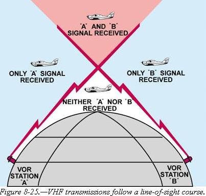
in the event of radio malfunction. • VHF Omnidirectional Range (VOR) Very High Frequency (VHF) Omnidirectional Range (VOR) The word “omni” means all, and an omnidirectional range is a VHF radio
transmitting ground station that projects straight line courses (radials) from
the station in all directions. From a top view, it can be visualized as being
similar to the spokes from the hub of a wheel. The distance VOR radials are
projected depends upon the power output of the transmitter.
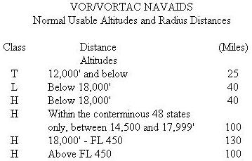
The useful range of certain facilities may be less than 50 miles. For further
information concerning these restrictions, refer to the Comm/NAVAID Remarks in
the Airport/Facility Directory.
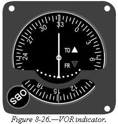
A list of these checkpoints is published in the Airport/Facility Directory. Basically, these checks consist of verifying that the VOR radials the airplane equipment receives are aligned with the radials the station transmits. There are not specific tolerances in VOR checks required for VFR flight. But as a guide to assure acceptable accuracy, the required IFR tolerances can be used which are ±4° for ground checks and ±6° for airborne checks. These checks can be performed by the pilot. The VOR transmitting station can be positively identified by its Morse code identification or by a recorded voice identification which states the name of the station followed by the word “VOR.” Many Flight Service Stations transmit voice messages on the same frequency that the VOR operates. Voice transmissions should not be relied upon to identify stations, because many FSS’s remotely transmit over several omniranges which have different names than the transmitting FSS. If the VOR is out of service for maintenance, the coded identification is removed and not transmitted. This serves to alert pilots that this station should not be used for navigation. VOR receivers are designed with an alarm flag to indicate when signal strength is inadequate to operate the navigational equipment. This happens if the airplane is too far from the VOR or the airplane is too low and therefore, is out of the line-of-sight of the transmitting signals. Using the VOR Using the VOR is quite simple once the basic concept is understood. The
following information, coupled with practice in actually using this equipment,
should erase all the mysteries and also provide a real sense of security in
navigating with the VOR.
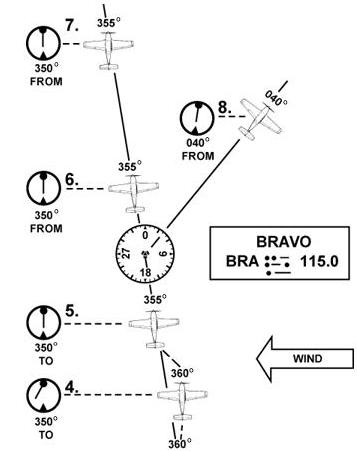
Tracking with Omni The following describes a step-by-step procedure to use when tracking to and from a VOR station. Figure 8-27 illustrates the discussion: • First, tune the VOR receiver to the frequency of the selected VOR station. For example: 115.0 to receive Bravo VOR. Next, check the identifiers to verify that the desired VOR is being received. As soon as the VOR is properly tuned, the course deviation needle will deflect either left or right; then rotate the azimuth dial to the course selector until the course deviation needle centers and the TO-FROM indicates “TO.” If the needle centers with a “FROM” indication, the azimuth should be rotated 180° because, in this case, it is desired to fly “TO” the station. Now, turn the aircraft to the heading indicated on the omni azimuth dial or course selector. In this example 350°. • If a heading of 350° is maintained with a wind from the right as shown, the airplane will drift to the left of the intended track. As the airplane drifts off course, the VOR course deviation needle will gradually move to the right of center or indicate the direction of the desired radial or track. • To return to the desired radial, the aircraft heading must be altered approximately 30° to the right. As the aircraft returns to the desired track, the deviation needle will slowly return to center. When centered, the aircraft will be on the desired radial and a left turn must be made toward, but not to the original heading of 350° because a wind drift correction must be established. The amount of correction depends upon the strength of the wind. If the wind velocity is unknown, a trial and error method can be used to find the correct heading. Assume, for this example a 10° correction or a heading of 360° is maintained. • While maintaining a heading of 360°, assume that the course deviation begins to move to the left. This means that the wind correction of 10° is too great and the airplane is flying to the right of course. A slight turn to the left should be made to permit the airplane to return to the desired radial. • When the deviation needle centers, a small wind drift correction of 5° or a heading correction of 355° should be flown. If this correction is adequate, the airplane will remain on the radial. If not, small variation in heading should be made to keep the needle centered, and consequently keep the airplane on the radial. • As the VOR station is passed, the course deviation needle will fluctuate then settle down, and the “TO” indication will change to “FROM.” If the aircraft passes to one side of the station, the needle will deflect in the direction of the station as the indicator changes to “FROM.” • Generally, the same techniques apply when tracking outbound as those used for tracking inbound. If the intent is to fly over the station and track outbound on the reciprocal of the inbound radial, the course selector should not be changed. Corrections are made in the same manner to keep the needle centered. The only difference is that the omni will indicate “FROM.” • If tracking outbound on a course other than the reciprocal of the inbound radial, this new course or radial must be set in the course selector and a turn made to intercept this course. After this course is reached, tracking procedures are the same as previously discussed. Tips on Using the VOR • Positively identify the station by its code or voice identification.
• When navigating to a station, determine the inbound radial and use this
radial. If the aircraft drifts, do not reset the course selector, but correct
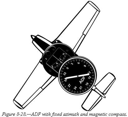
for drift and fly a heading that will compensate for wind drift. Automatic Direction Finder Many general aviation-type airplanes are equipped with automatic direction finder (ADF) radio receiving equipment. To navigate using the ADF, the pilot tunes the receiving equipment to a ground station known as a NONDIRECTIONAL RADIOBEACON (NDB). The NDB stations normally operate in a low or medium frequency band of 200 to 415 kHz. The frequencies are readily available on aeronautical charts or in the Airport/Facility Directory. All radiobeacons except compass locators transmit a continuous
three-letter identification in code except during voice transmissions. A compass
locator, which is associated with an Instrument Landing System, transmits a
two-letter identification. Nondirectional radiobeacons have one advantage over the VOR. This advantage is that low or medium frequencies are not affected by line-of-sight. The signals follow the curvature of the Earth; therefore, if the aircraft is within the range of the station, the signals can be received regardless of altitude. The following table gives the class of NDB stations, their power, and usable range: NONDIRECTIONAL RADIOBEACON (NDB) * Service range of individual facilities may be less than 50 miles.
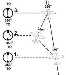
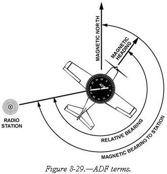
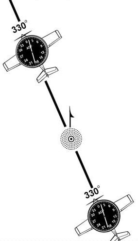
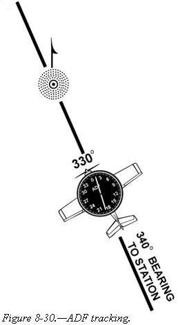
To determine the magnetic bearing “FROM” the station, 180° is added to or subtracted from the magnetic bearing to the station. This is the reciprocal bearing and is used when plotting position fixes. Keep in mind that the needle of fixed azimuth points to the station in relation to the nose of the aircraft. If the needle is deflected 30° to the left or a relative bearing of 330°, this means that the station is located 30° left. If the aircraft is turned left 30°, the needle will move to the right 30° and indicate a relative bearing of 0° or the aircraft will be pointing toward the station. If the pilot continues flight toward the station keeping the needle on 0°, the procedure is called homing to the station. If a crosswind exists, the ADF needle will continue to drift away from zero. To keep the needle on zero, the aircraft must be turned slightly resulting in a curved flightpath to the station. Homing to the station is a common procedure, but results in drifting downwind, thus lengthening the distance to the station. Tracking to the station requires correcting for wind drift and results in
maintaining flight along a straight track or bearing to the station. When the
wind drift correction is established, the ADF needle will indicate the amount of
correction to the right or left. For instance, if the magnetic bearing to the
station is 340°, a correction for a left crosswind would result in a magnetic
heading of 330°, and the ADF needle would indicate 10° to the right or a
relative bearing of 010°. [Figure 8-30]
When tracking away from the station, wind corrections are made similar to
tracking to the station but the ADF needle points toward the tail of the
aircraft or the 180° position on the azimuth dial. Attempting to keep the ADF
needle on the 180° position during winds results in the aircraft flying a curved
flight leading further and further from the desired track. To correct for wind
when tracking outbound, correction should be made in the direction opposite of
that in which the needle is pointing. Other Navigational Systems There are other navigational systems which are more advanced such as long range navigation (LORAN-C) and global positioning system (GPS). The long range navigation uses a network of land-based radio transmitters developed to provide an accurate system for long range navigation. The system is based upon the measurement of the difference in time of arrival of pulses of radio-frequency energy radiated by a group or chain of transmitters which are separated by hundreds of miles. The global positioning system is a satellite-based radio positioning, navigation, and time-transfer system developed by the U.S. Department of Defense. The concept of GPS is based on accurate and continuous knowledge of the spatial position of each satellite in the system. GPS provides accurate information 24 hours a day and is unaffected by the weather. If more detailed information on these systems is desired, the pilot may reference the Aeronautical Information Manual. Since both LORAN and GPS have various presentations, a pilot should refer to the Aircraft Flight Manual for the individual make and model for proper usage.
|