| Latitude and Longitude (Meridians and Parallels)
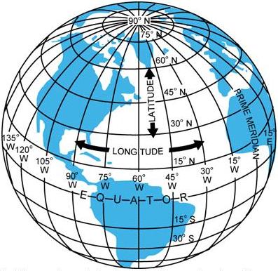
The Equator is an imaginary circle equidistant from the poles of the
Earth. Circles parallel to the Equator (lines running east and west) are
parallels of latitude. They are used to measure degrees of latitude north or
south of the Equator. The angular distance from the Equator to the pole is
one-fourth of a circle or 90°. The 48 conterminous states of the United States
are located between 25° and 49° N. latitude. The arrows in figure 8-2 labeled
“LATITUDE” point to lines of latitude.
Meridians of longitude are drawn from the North Pole to
the South Pole and are at right angles to the Equator. The “Prime
Meridian” which passes through Greenwich, England, is used as the zero
line from which measurements are made in degrees east and west to 180°.
The 48 conterminous states of the United States are between 67° and 125°
W. Longitude. The arrows in figure 8-2 labeled “LONGITUDE” point to lines
of longitude.
Any specific geographical point can thus be
located by reference to its longitude and latitude. Washington, DC for
example, is approximately 39° N. latitude, 77° W. longitude. Chicago is
approximately 42° N. latitude, 88° W. longitude.
Time Zones
The meridians are also useful for designating time zones. A day
is defined as the time required for the Earth to make one complete
revolution of 360°. Since the day is divided into 24 hours, the Earth
revolves at the rate of 15° an hour. Noon is the time when the Sun is
directly above a meridian; to the west of that meridian is forenoon, to
the east is afternoon. |
|
|
Figure 8-2.—Meridians and parallels—the basis of measuring time,
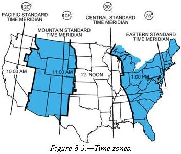
distance, and direction. | The standard practice is
to establish a time zone for each 15° of longitude. This makes a difference of
exactly 1 hour between each zone. In the United States, there are four time
zones. The time zones are Eastern (75°), Central (90°), Mountain (105°), and
Pacific (120°). The dividing lines are somewhat irregular because communities
near the boundaries often find it more convenient to use time designations of
neighboring communities or trade centers. Figure 8-3 shows the time zones in the
United States. When the Sun is directly above the 90th meridian, it is noon
Central Standard Time. At the same time, it will be 1 p.m. Eastern Standard
Time, 11 a.m. Mountain Standard Time, and 10 a.m. Pacific Standard Time. When
“daylight saving” time is in effect, generally between the last Sunday in April
and the last Sunday in October, the Sun is directly above the 75th meridian at
noon, Central Daylight Time.
These time zone differences must be taken into account during long
flights eastward—especially if the flight must be completed before dark.
Remember, an hour is lost when flying eastward from one time zone to another, or
perhaps even when flying from the western edge to the eastern edge of the same
time zone. Determine the time of sunset at the destination by consulting the
flight service stations (AFSS/FSS) or National Weather Service and take this
into account when planning an eastbound flight.
 |
In most aviation operations, time is expressed in terms of the 24-hour
clock. Air traffic control instructions, weather reports and broadcasts,
and estimated times of arrival are all based on this system. For example:
9 a.m. is expressed as 0900; 1 p.m. is 1300; 10 p.m. is 2200 etc.
Because a pilot may cross several time zones during a flight, a
standard time system has been adopted. It is called Universal Coordinated
Time (UTC) and is often referred to as Zulu time. UTC is the time at the
0° line of longitude which passes through Greenwich, England. All of the
time zones around the world are based on this reference. To convert to
this time, a pilot should do the following:
• Eastern Standard Time
Add 5 hours
• Central Standard Time Add 6 hours
• Mountain
Standard Time Add 7 hours
• Pacific Standard Time Add 8 hours
For daylight saving time, 1 hour should be subtracted from the
calculated times. |
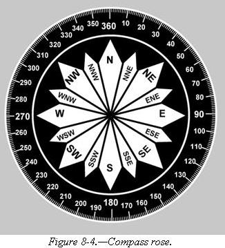
| Measurement of Direction
By using the meridians, direction from one point to another can
be measured in degrees, in a clockwise direction from true north. To
indicate a course to be followed in flight, draw a line on the chart from
the point of departure to the destination and measure the angle which this
line forms with a meridian. Direction is expressed in degrees, as shown by
the compass rose in figure 8-4.
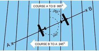
Because meridians converge toward the poles, course measurement should
be taken at a meridian near the midpoint of the course rather than at the
point of departure. The course measured on the chart is known as the true
course. This is the direction measured by reference to a meridian or true
north. It is the direction of intended flight as measured in degrees
clockwise from true north. As shown in figure 8-5, the direction from A to
B would be a true course of 065°, whereas the return trip (called the
reciprocal) would be a true course of 245°. |
 |
 |
The true heading is the direction in which the nose of the airplane
points during a flight when measured in degrees clockwise from true north.
Usually, it is necessary to head the airplane in a direction slightly
different from the true course to offset the effect of wind. Consequently,
numerical value of the true heading may not correspond with that of the
true course. This will be discussed more fully in subsequent sections in
this chapter. For the purpose of this discussion, assume a no-wind
condition exists under which heading and course would coincide. Thus, for
a true course of 065°, the true heading would be 065°. To use the compass
accurately, however, corrections must be made for magnetic variation and
compass deviation. |
Variation
Variation is the angle between true north and magnetic north. It is
expressed as east variation or west variation depending upon whether magnetic
north (MN) is to the east or west of true north (TN), respectively.
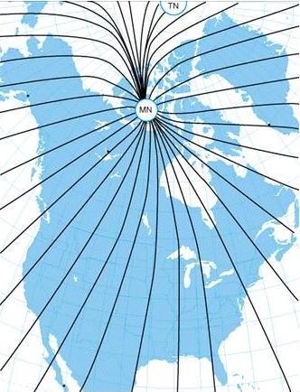
| The north magnetic pole is located close to 71° N. latitude, 96° W.
longitude and is about 1,300 miles from the geographic or true north pole,
as indicated in figure 8-6. If the Earth were uniformly magnetized, the
compass needle would point toward the magnetic pole, in which case the
variation between true north (as shown by the geographical meridians) and
magnetic north (as shown by the magnetic meridians) could be measured at
any intersection of the meridians.
Actually, the Earth is not uniformly magnetized. In the United States
the needle usually points in the general direction of the magnetic pole,
but it may vary in certain geographical localities by many degrees.
Consequently, the exact amount of variation at thousands of selected
locations in the United States has been carefully determined. The amount
and the direction of variation, which change slightly from time to time,
are shown on most aeronautical charts as broken magenta lines, called
isogonic lines, which connects points of equal magnetic variation. (The
line connecting points at which there is no variation between true north
and magnetic north is the agonic line.) An isogonic chart is shown in
figure 8-6. Minor bends and turns in the isogonic and agonic lines are
caused by unusual geological conditions affecting magnetic forces in these
areas. |
|
|
Figure 8-6.—Isogonic chart. Magnetic meridians are in black,
geographic meridians and parallels are in blue. Variation is the angle
between a magnetic and geographic meridian. |
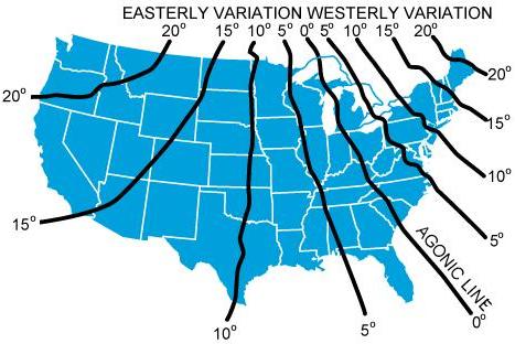 |
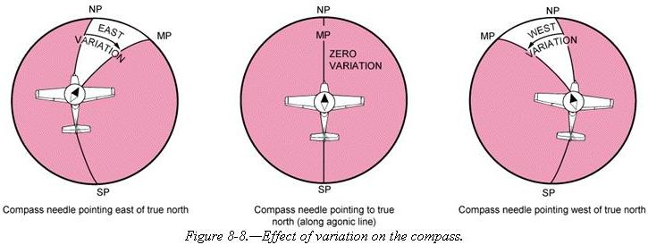
On the west coast of the United States, the compass needle points to
the east of true north; on the east coast, the compass needle points to
the west of true north. Zero degree variation exists on the agonic line
which runs roughly through Lake Michigan, the Appalachian Mountains, and
off the coast of Florida, where magnetic north and true north coincide.
[Compare figures 8-7 and 8-8]
Because courses are measured in reference to geographical meridians
which point toward true north, and these courses are maintained by
reference to the compass which points along a magnetic meridian in the
general direction of magnetic north, the true direction must be converted
into magnetic direction for the purpose of flight. This conversion is made
by adding or subtracting the variation which is indicated by the nearest
isogonic line on the chart. The true heading, when corrected for
variation, is known as magnetic heading. |
| Figure 8-7.—A typical isogonic chart. The black lines are isogonic
lines which connect geographic points with identical magnetic
variation. |
|
 |
If the variation is shown as “9° E,” this means that magnetic north is 9°
east of true north. If a true heading of 360° is to be flown, 9° must be
subtracted from 360°, which results in a magnetic heading of 351°. To fly east,
a magnetic heading of 081° (090° - 9°) would be flown. To fly south, the
magnetic heading would be 171° (180° - 9°). To fly west, it would be 261° (270°
- 9°). To fly a true heading of 060°, a magnetic heading of 051° (060° - 9°)
would be flown.
Remember, to convert true course or heading to magnetic course or
heading, note the variation shown by the nearest isogonic line. If variation is
west, add; if east, subtract. One method for remembering whether to add or
subtract variation is the phrase “east is least (subtract) and west is best
(add).”
Deviation
Determining the magnetic heading is an intermediate step necessary to obtain
the correct compass reading for the flight. To determine compass heading, a
correction for deviation must be made. Because of magnetic influences within the
airplane such as
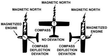
| electrical circuits, radio, lights, tools, engine, magnetized metal
parts, etc., the compass needle is frequently deflected from its normal
reading. This deflection is deviation. The deviation is different for each
airplane, and it also may vary for different headings in the same
airplane. For instance, if magnetism in the engine attracts the north end
of the compass, there would be no effect when the plane is on a heading of
magnetic north. On easterly or westerly headings, however, the compass
indications would be in error, as shown in figure 8-9. Magnetic attraction
can come from many other parts of the airplane; the assumption of
attraction in the engine is merely used for the purpose of
illustration. |
|
|
Figure 8-9.—Magnetized portions of the airplane cause the compass
to deviate from its normal indications. |
Some adjustment of the compass, referred to as compensation, can be made to
reduce this error, but the remaining correction must be applied by the pilot.
Proper compensation of the compass is best performed by a competent
technician. Since the magnetic forces within the airplane change, because of
landing shocks, vibration, mechanical work, or changes in equipment, the pilot
should occasionally have the deviation of the compass checked. The procedure
used to check the deviation (called “swinging the compass”) is briefly outlined.
The airplane is placed on a magnetic compass rose, the engine started,
and electrical devices normally used (such as radio) are turned on.
Tailwheel-type airplanes should be jacked up into flying position. The airplane
is aligned with magnetic north indicated on the compass rose and the reading
shown on the compass is recorded on a deviation card. The airplane is then
aligned at 30° intervals and each reading is recorded. If the airplane is to be
flown at night, the lights are turned on and any significant changes in the
readings are noted. If so, additional entries are made for use at night.
The accuracy of the compass can also be checked by comparing the
compass reading with the known runway headings.
On the compass card,
the letters, N, E, S, and W, are used for north, east, south, and west. The
final zero is omitted from the degree markings so that figures will be larger
and more easily seen.
A deviation card, similar to figure 8-10, is mounted near the compass,
showing the addition or subtraction required to correct for deviation on various
headings, usually at intervals of 30°. For intermediate readings, the pilot
should be able to interpolate mentally with sufficient accuracy. For example, if
the pilot needed the correction for 195° and noted the correction for 180° to be
0° and for 210° to be +2°, it could be assumed that the correction for 195°
would be +1°. The magnetic heading, when corrected for deviation, is known as
compass heading.
Figure 8-10.—Compass deviation card.
FOR (MAGNETIC) N 30 60 E 120 150
STEER (COMPASS) 0 28
57 86 117 148
FOR (MAGNETIC) S 210 240 W 300 330
STEER
(COMPASS) 180 212 243 274 303 332 |
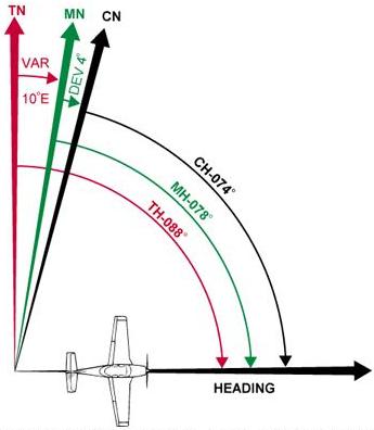
The following method is used by many pilots to determine compass
heading:
After the true course (TC) is measured, and wind correction
applied resulting in a true heading (TH), the sequence TH ± V = MH ± D =
CH is followed to arrive at compass heading. [Figure 8-11]
|
|
|
Figure 8-11.—Relationship between true, magnetic, and compass
headings for a particular instance. |
|